One Line Drawing Stacked Pipes Plan
Introduction to Piping Transportation – Engineering
In Part one we learnt most pipes, while in Part 2 we learnt near Planning and Scheduling of pipe transport operations. In this part, we volition larn about Technology.
Phase iii – Engineering science.
Engineering for pipe transportation is an intriguing subject. The shape of the cargo demands unique ways of stowage and lifting. The whole do of engineering has two categories – 1. Calculations for pipes 2. Transportation Assay for vessels
Category 1 – Calculations and Analyses for the pipes.
The pipes to exist transported may be of varying dimensions and weight, and each pipe blazon needs to exist studied for its own requirements of lifting and stowage. Two major calculations related to the pipes are discussed below
- Stacking Peak calculations – for each type of pipe included in the project, the stacking top limit should be calculated. The stowage of each pipage type will be governed past its stacking height limit. We discussed in the section on 'Pipes' as to how stacking height limit is to be determined. The reader may also refer to our product 'Stacking Meridian Figurer for Bare Pipes'
- Lifting programme and lifting calculations
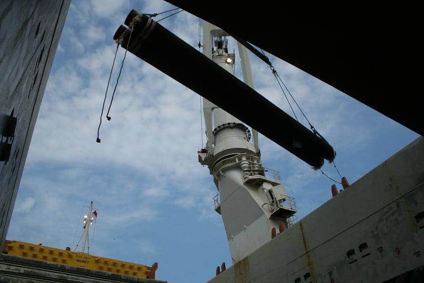
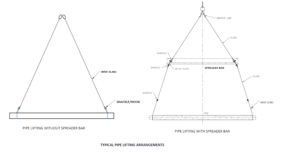
Pipes need to be lifted at the yard to exist loaded on to the vessel. They as well demand to be lifted from the vessel to exist fed to the lay barge. Thus, a lifting plan for the pipes needs to exist in identify. A uncomplicated lifting configuration for pipes is to have a ii-sling lifting arrangement. In this organization, i end of each sling is connected to the pipe while the other end goes to the crane hook. The terminate connected to the pipe has a soft eye which is large plenty to accommodate the pipage. Masterlinks are used to connect to the claw cease. In some cases, a spreader bar is used betwixt the crane hook and the pipe. Separate slings are used to connect between crane hook & spreader, and between the spreader bar & pipe. Shackles are used to connect between the pipe and slings. Using a spreader leads to smaller slings being used which may be operationally more manageable. In some cases, a webbing sling may be used to go around the pipage. The lifting programme should be prepared in thorough discussions with the Operations team. In some cases, more one lifting plan may have to be prepared to cater to dissimilar pipe types being lifted.
Whatever lifting organisation is used, the lifting plan must clearly state the specifications and quantity of each item used in lifting. Further, for each lifting plan prepared, a supporting lifting calculation must be prepared to demonstrate the adequacy of the lifting organisation. GL Noble Denton Guidelines (Ref [two], ND-0027) is the guiding document for lifting pattern. Following points may be helpful which doing the lifting calculations
- Dynamic Loads – The loads on the slings will incorporate of the self-weight of the pipe, also as any dynamic loads expected. Unremarkably, dynamic loads are higher offshore compared to yard. A dominion of thumb is to take a cistron of i.3 for dynamic load. If a spreader bar is present, its weight must exist included in calculations for upper slings and fastenings
- Force check – Each item of the lifting arrangement must be checked for its strength. These include the shackles, pad-eyes, slings, spreader confined, webbing slings, masterlink, delta plate etc. Usually a cheque against WLL is sufficient, but in some cases Shear and Bending Stresses need to be checked too.
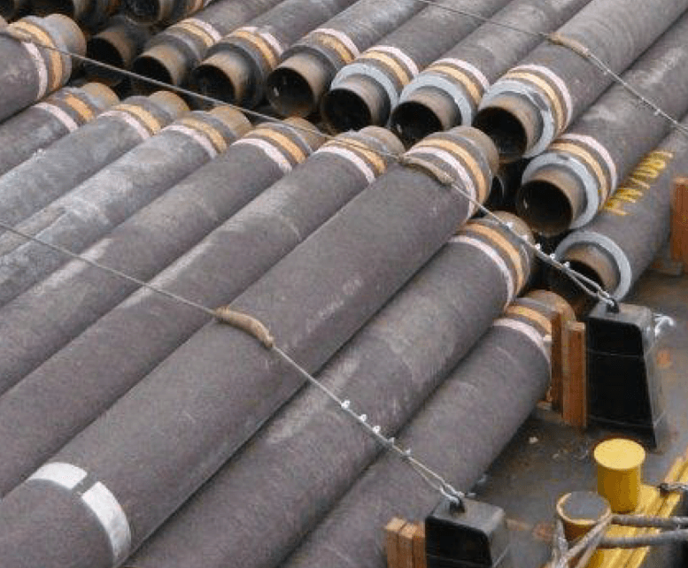
- Lifting multiple pipes – If the pipes are of smaller size and weight, multiple pipes may be lifted at a fourth dimension by using multiple webbing slings (see movie below)
- MWS Approval – The Lifting programme and calculations should be submitted to the MWS for approval before any operation commences.
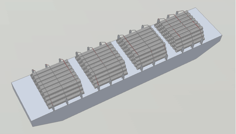
Category two – Transportation Assay for the vessel(s). Once the pipe calculations and lifting plan are available, the next step is to behave out the detailed Transportation Analysis for the vessel(s) involved in the send. The purpose of this Assay is to demonstrate the suitability of the vessel(southward) for the send. We will etch out a step-by-step process beneath for carrying out a Transportation Assay Footstep 1 – Gear up the vessel's stowage plan (stowage on deck) The first activeness required is to set a stowage programme for the selected vessel. For simplicity, we volition limit give-and-take to vessels which can stow only on the deck. Stowage in Cargo holds will non exist covered in this commodity. What is a stowage plan? Information technology is a plan showing the way pipes are going to be loaded on the vessel. Let's take an example of a simple clomp of length 76 m and width 30 one thousand. Let the clear bachelor deck space on the vessel be 66 m x 26 g. Pipes are to be loaded on this vessel. Pipes are generally stacked with their lengths oriented along the length of the vessel. This is chosen Longitudinal stacking. Pipes tin also exist stacked with their lengths along the vessel'due south width (Transverse stacking) but information technology is not a preferred method. A unproblematic style to prepare a stowage plan tin can be as below:
- Load pipes on the forrad end of the available deck infinite. The bottom tier will bridge 26 m wide. Continue loading tiers above the lesser tier till the stacking height limit is reached. This is the first stack of pipes. It is also called a 'Bay'. Its length is the length of one pipe = 12.two yard.
- Start loading pipes behind (or aft of) the fwd Bay. For lifting and manual handling of pipes, nosotros need to keep a clear spacing between the fwd Bay and the second bay (minimum 400 mm). In a similar fashion, keep loading pipes in 2nd bay till the stacking height limit is reached.
- Load the next Bay aft of the previous i. Keep repeating this procedure till the aft stop of the available deck space is reached.
Loading in the above manner, we will arrive at a stowage programme as shown in the figure below. 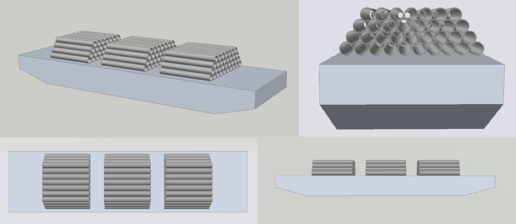 A simple adding for number of bays and their spacing Usually the number of bays possible to be loaded on the vessel can be decided from some initial calculations. We will derive the formula for the number of trophy possible. Let the available length of deck space be Fiftyd, the spacing between trophy be southward, and the length of a bay (same as pipe length) be lp. Let the number of bays be northB. The number of spacings between bays is ane less than the number of bays.
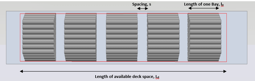
From the figure shown, nosotros can write a simple relationship Length of bay x number of bays + spacing x number of spacings = Length of deck The number of spacings is one less than the number of bays. Thus, lp ten nB + s x (nB – i) = Ld
- s = (50d – nB ten 50p)/ (northwardB -1) …………………………..Eq(ane)
- Let the minimum spacing required be smin. Thus s >= due southmin
- (Ld – nB x lp)/ (nB – one) >= southmin
- n <= (Ld + southwardmin)/ (fiftyp + southmin) …………………………….Eq(2)
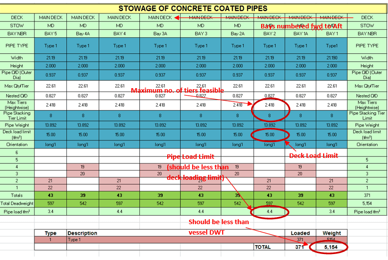
In the present example, 50d = 66 m, lp = 12.2 one thousand, smin = 0.four m. This gives northward <= 5.26. Since n must be an integer, n <= 5. Thus, the maximum number of bays possible is 5. Using this nB = five in the Eq(1), nosotros become the actual spacing betwixt bays every bit s = (66 – v x 12.2)/(5-1) = 1.25 k or 1250 mm. Excel Spreadsheet Ane good fashion of representing the stowage programme is to use an excel spreadsheet. Once the number of trophy is known, we tin can create a spreadsheet showing all the bays, and the number of pipes stacked in each bay. The spreadsheet can likewise be used to summate the total weight of pipes in each bay and on the vessel.
Here it is useful to highlight some points regarding preparing a stowage program
- Numbering of bays – Normally trophy are numbered beginning from fwd finish. The foremost bay is Bay No. 1, the one aft of it is Bay No. ii and so on.
- Deck Loading Limit – The deck of the vessel volition have a limit to the load it can take. It is usually specified in tons per sq. grand. In the spreadsheet, the deck loading of each bay must be calculated, and it should be ensured that the deck loading limit of the vessel is not breached. Information technology may and so happen that we may non exist able to load pipes upto the stacking limit considering the deck loading is reached before.
- Peak restrictions for manual handling – For manual treatment of pipes, there are restrictions on the maximum height of a bay of pipe on deck. Generally, a maximum height of ii thousand is followed. It may happen that the stacking summit limit of the pipe is more than 2 m. In such a instance, the maximum tiers possible will be dictated past the height restriction of ii 1000, and non by the stacking summit limit.
- Trim by aft – Usually in marine transportation, a slight trim by aft is preferred when the vessel is in sea (see Ref[2] ND 0030). This tin can be achieved past ballasting the vessel. However, trim by aft can besides exist achieved by arranging the pipes and adding more pipes aft than forward. This is a sensitive exercise and should be done with caution.
- Vessel's capacity – We may be able to load pipes on all trophy upto the stacking height limit, but the total weight of pipes loaded must be less than the maximum Deadweight (carrying capacity) of the vessel. If the total weight of pipes is exceeding the deadweight, then pipes should be removed till the total weight of pipes is less than the deadweight.
- Multiple pipe types in holds and deck – If two or more different types of pipes are being loaded in a vessel which has loading in both holds and deck, so the pipes which are to be unloaded first should be loaded on deck, and those to be unloaded later should exist loaded in holds.
From the to a higher place we tin see that preparing a stowage programme is an practice fraught with multiple constraints, and requires caution and experience. thanavalarch has its own spreadsheet adult for pipe stowage plans on vessels with but deck loading. You may check it hither. Step two – Study the route and environmental Parameters
Source: pixabay
The next footstep is to collect the data on the environment which the vessel will feel forth the road. The information includes the wind, wave, and electric current parameters. These are very critical inputs in the analysis, considering they volition determine the forces which the vessel and the pipes feel in the body of water. Environment data can be obtained from Nautical Charts, or from a data provider similar Metocean. The information for the relevant window of send should be obtained, and the most extreme environment during the window should be used for further analysis. Reading and extracting environment information is a carve up exercise, and will non be dealt with in this commodity. We will motion on to the next step – the Transport's trim, stability, and strength evaluation. Stride 3 – Evaluating Vessel's Trim, Stability and Strength
Now nosotros accept a stowage plan at mitt, we would like to know what will be the floating condition of the vessel when loaded with pipes. Nosotros would too similar to check the vessel's stability and strength in this loading condition. For this, we need to know the vessel's hydrostatics and other geometric backdrop like cross curves etc. Depending on the data availability, dissimilar approaches may be employed:
- If the vessel has a loading calculator onboard, then the stowage plan can exist sent to the vessel'southward Master who performs the stability and strength evaluation and sends back the report. By and large loading computers are installed onboard all merchant vessels, but not on unmanned barges.
- If the vessel doesn't have a loading estimator, only if it has stability booklet with all required information (like trimmed hydrostats and cross curves), and then paw calculations tin be performed to check trim and stability. Notwithstanding, manus calculations are not always authentic and dependable.
- If the vessel doesn't have loading computer or reliable data, then the stability can be evaluated past modeling it in a computer software similar GHS, Maxsurf, NAPA, Autohydro etc. For this, the linesplan of the vessel should be available. Generally, this method is adopted for barges, for whom apparent data or loading computer is not available.
Preparing the loading plan The loading plan of the vessel will include, autonomously from the pipes to be stowed, the amount of liquids like ballast, fuel oil etc. which volition be used onboard. When preparing a loading plan, following points are helpful:
- Draft restrictions – At that place may be draft restrictions at the loading/unloading locations. The stowage programme and loading plan should be prepared keeping these in mind
- Trim by aft – Loading plan should preferably exist prepared to provide a slight trim by aft. In whatsoever example, a trim by fwd is non acceptable, and should be avoided at any cost
- Grunter and Sag – Tanks should be ballasted to avert making the vessel experiencing also much grunter or sag. For example, if the pipes take been loaded more around the midship, the vessel volition tend to sag. In such case, anchor tanks of aft and frontwards should be utilized to correct the sag. If ballast tanks effectually midship are filled, the sag will increment and longitudinal strength may be compromised.
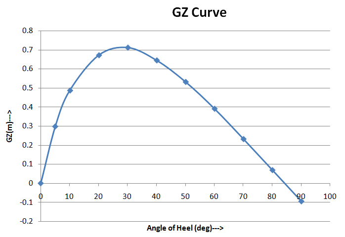
Checking Floatation, Stability and Force One time the Loading plan is prepared, we can check the equilibrium floating condition of the vessel. The floating hydrostatics will provide the typhoon, heel, trim, VCG, KM, GM etc. The floating status stability should be evaluated confronting the standard rules of IMO Stability. Conventional IMO rules relate to sea going merchant vessels equally per IMO RESOLUTION A.749 (18) Ch 3. At that place are carve up IMO rules for Stability of non-self-propelled Barges. These are in IMO Res A 749(10) Sec 4.7. These can be followed for barges. For conventional ships, both deviation and arrival weather should be checked. For towed barges, only i loading condition needs to exist checked. The longitudinal strength of the vessel should be checked using a computer software. The Shear Forcefulness and the Bending Moments resulting from the check should be within the limits of the vessel. In a vessel with loading computer, the limits are available. However, for vessels like Barges, these limits are not available, and they can be calculated from some Class rules bachelor (e.yard., ABS Rules for Barges). If the longitudinal force requirement is not met, and so the loading condition is not appropriate. It needs to be modified. For instance, if the vessel is failing in sagging condition, this means there is too much load well-nigh midship. The load needs to be transferred to fwd and aft parts of the vessel. This can exist done using anchor tanks. In some cases, rearranging the pipes (provided at that place is infinite) tin can also achieve the desired results. Stride 4 – Motions Analysis
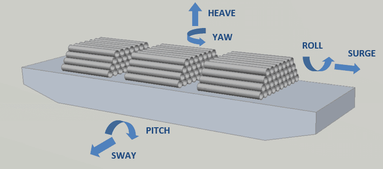
At this phase, the stowage plan has been prepared and stability of the vessel evaluated. Next step is to do a motions assay of the cargo (i.e., pipes). What is a motions assay and why exercise we need it? A motions analysis is an assay done in a computer software to calculate the motions and accelerations which the vessel and its cargo will experience in the body of water in the given environment. The results of motions analysis are the forces/accelerations acting on the cargo in the 3 directions – Longitudinal, Transverse and Vertical. It also gives the maximum magnitude of the six motions of the vessel – scroll, pitch, boost, surge, sway and yaw. Motions analysis requires sophisticated computer software. In case a motions analysis cannot exist performed, the alternative is to follow industry guidelines like Nobledenton Guidelines for Marine Transportations (Encounter Ref[ane] ND-0030, Sec vii.9). From motions analysis, we will know the motions and accelerations at the different bays of pipes. The most conservative results volition further be utilized for seafastening calculations. Readers may like to check thenavalarch's product 'Cargo Forces and Accelerations' based on Ref[1] ND-0030. Considering its vastness, a detailed discussion on motions analysis is out of scope of this article. We will move on to the next step which is seafastening calculations for the pipes. Step 5 – Seafastening Calculations
Perhaps the virtually niche department of the Transportation Analysis is the seafastening calculations for the pipes. Due to the unique shape and stowage plan of the cargo, unique engineering solutions have to be deployed for the seafastening of pipes. Get-go, what do nosotros hateful by seafastening calculations? Seafastening is the fashion the cargo will be 'fastened' or secured to the deck of the transport during transport. It is obvious that we cannot be transporting the stacked pipes on the ship without somehow securing them to the deck. This is considering the pipes are discipline to forces and motions (encounter previous section), and they may be lost to the body of water if not secured. Talking about securing pipes to the deck, the first solution which comes to mind is to tie ropes around them and secure these ropes to the deck of the ship. This actually is the way pipes are secured to the deck of the ship. Nevertheless, this is non the complete picture. Let us consider one-by-i all the different forces and motions which the pipes feel, and what securing solution to devise for them.
- Rolling motility of the send (pipe overturning) – when the ship rolls to one side, the pipes loaded on the send tend to curl over. This is called the overturning of pipes, and is depicted below.
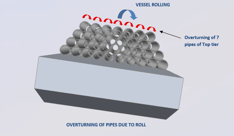
Rolling leads to an overturning moment on the pipage. To prevent this overturning, lashing ropes tin can be utilized. These ropes run across the bay of pipe and are secured to the deck. From engineering calculations, it should be demonstrated that the ropes are strong enough to contain the overturning of a complete tier of pipes. These are called pipe overturning calculations. Pad-optics are welded on the deck to secure these ropes to the deck. The calculations should besides demonstrate the capability of the forcefulness of pad-eyes.
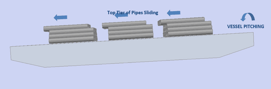
- Pitching motion of the transport and longitudinal forces (pipe sliding) – when the ship pitches, the pipe tilts forth its length. Due to this tilt, at that place is slipping between two tiers of pipes. The top tier of the piping may slide over the tier below. Slipping besides depends on the magnitude of pitching experienced. The longitudinal force experienced past the vessel adds to this sliding force.
In virtually cases if the pipes are physical coated, the friction betwixt two tiers of pipes is sufficient to preclude the slipping due to pitching. However, in cases of bare pipes existence shipped, or when the pitching is high enough to cause sliding, then arrangements accept to be made to prevent the sliding of pipes. One method is to design longitudinal stoppers to hold the pipes longitudinally. Other method is to use anti-friction rubber mats placed betwixt tiers of pipes to better friction between the tiers. Technology calculations are required to be done for checking the sliding of pipes and nowadays solution required. This is called 'Piping sliding verification'
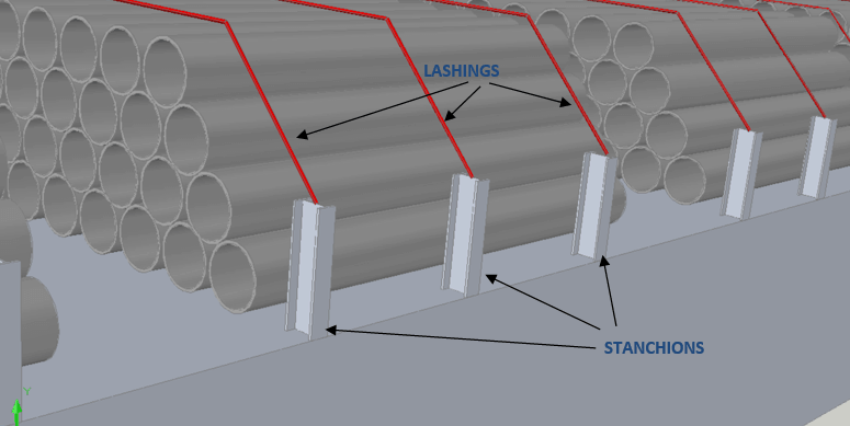
- Transverse forces on transport and stanchions – the transverse acceleration of the ship results in the bay of pipes swaying to the side of the vessel. While lashing across the bay prevents the overturning of the pipes, it may not be sufficient to hold the pipes from swaying. This transverse motion of the pipes is contained by providing 'stanchions' on the ship. A stanchion is a vertical beam which is welded to the deck of the ship. More often than not for piping ship operations, an I-beam stanchion is the most preferred design. The pipe bays remainder on the stanchions on the sides (see figure beneath). All the transverse forces on the pipe trophy are taken past these stanchions. A vessel may have existing stanchions which may be utilized, or new stanchions may be welded, depending on the requirements and forces experienced. In any example, engineering calculations and analyses are required to demonstrate that the stanchions are fit for the purpose. Sometimes a FE Analysis may as well be needed.
- Vertical forces and dunnage crushing – In improver to the cocky-weight of the pipes, heave forces due to send motion also act on the deck of the vessel. The deck of the vessel takes this combined force. Unremarkably, the pipes are non loaded directly to the deck, and there are wooden planks (called dunnage) which are placed betwixt pipes and deck. The dunnage needs to be thick enough to take the dynamic vertical loads. The contact area betwixt pipes and dunnage is small (because pipes have round department), then the compressive stress on dunnage is expected to exist high. This stress needs to be evaluated, and dunnage appropriately selected to fit the requirements. This is called 'Dunnage burdensome verification'
Step six – Lashing Design
Based on the results of Seafastening design, the whole lashing plan to secure the pipes to the vessel needs to be prepared. The following items are office of the lashing plan of the vessel.
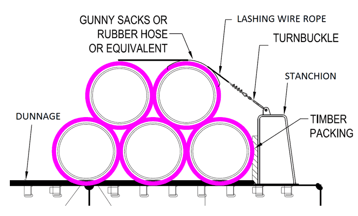
- Lashing ropes to prevent overturning – Wire ropes are by and large used for this purpose. Mostly, wire ropes with both ends soft-center are utilized.
- Pad-eyes or D-rings – Pad-optics or D-rings of adequate strength need to be welded to the deck of the vessel to tie the lashing ropes. In some cases, pad-eyes are welded to the top of stanchions.
- Shackles – to connect the pad-center to the lashing wire rope
- Turnbuckles – may exist needed to secure wire rope to deck
- Wire rope clips – for soft end of ropes
- Timber dunnage (planks) – to exist placed between piping trophy and deck, and too betwixt stanchion and pipes
- Gunny sacks or safety hose – To protect the pipe from damage by wire rope, gunny sacks can be placed between pipe and rope, or prophylactic hoses can exist fitted to the wire ropes.
The lashing plan should clearly show the locations, specification and quantity of each lashing item utilized. A elementary lashing plan is shown below (only for reference)
Lashing in Cargo Holds
- For lashing in cargo holds, in that location is no need for stanchions, since the walls of the hold provide the securing against transverse forces.
- To check overturning on partially loaded holds, a few pipes on top tiers may be bundled together using rachet straps to forestall the overturning.
- If sliding occurs, the stoppers/safety mats are required in holds besides
- Holds may also have tween decks. In such cases, the loading on the tween decks should be carefully planned so as not to exceed the loading limit on the tween deck pontoons
Too the stowage program, the lashing program is the most of import certificate for the operations team. They follow it religiously, then it should exist prepared with great care and caution so equally to avoid whatsoever hassles in operations. Step 7 –Bollard Pull Calculations and Towing plan
Epitome Courtesy – www.pixabay.com
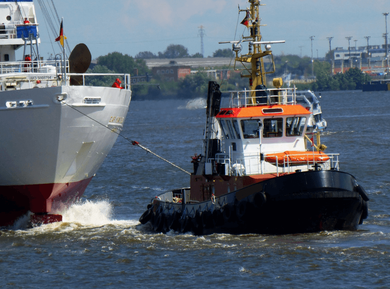
This step is applicable only when the vessel is a towed vessel, e.grand., a not-cocky-propelled barge. For such vessels, a tug needs to exist engaged to pull the vessel to location. The size of the tug will depend on the forcefulness required to pull the vessel in a given environment. The calculation to determine this strength is called Bollard Pull calculation. Following are the steps to acquit out this calculation
- Get the environment parameters. These are the current of air speed, electric current speed, and pregnant wave height of the tow road. In case the environment data are not available, the standard open up ocean weather condition as specified in Ref [1] ND-0030 may be used. It specifies a wind speed of forty knots, current speed of one knot and pregnant wave height of 5 thousand.
- Calculate the ecology forces on the vessel due to the wind, current and wave.
- Wind force calculation volition crave transverse windage area of the cargo and vessel.
- Electric current force is calculated from the underwater surface area of the vessel and current speed
- Waves atomic number 82 to an added wave resistance force on the vessel. This can be computed using standard references like Ref [v] DNV-Bone-H103 Sec 7.ii.half-dozen
- In one case total force is calculated, divide it past towing efficiency of the tug to obtain the required bollard pull.
- The selected tug'south bollard pull must be greater than the required bollard pull.
thenavalarch has its own spreadsheets for Bollard Pull calculations for Barges and Ships. You tin can check them hither. Once the Bollard Pull is known, a towing programme of the vessel is to be prepared. The guidance to be followed is in Ref [1] ND-0030. A standard towing organization with two smit brackets, two towing bridles, a delta plate and a towing rope is shown below. The towing plan should clearly specify the items to be used for towing, their ratings and quantity. A typical towing plan for a clomp looks like this (source, Ref [one] ND-0030)
Image Source – GL Noble Denton Guidelines for Marine Transportation, ND-0030
Similarly, an emergency towing programme needs to be prepared every bit per requirements in ND-0030 (Ref [i]). This should too specify all the required items for emergency towing of the vessel. A typical Emergency towing programme for a Barge may look like this (source ND-0030, Ref [one])
Epitome Source – GL Noble Denton Guidelines for Marine Transportation, ND-0030
That brings u.s. to the finish of this section on Transportation Analysis. The entire transportation assay document needs approval from the Marine Warranty Surveyor (MWS) before the bodily operations can brainstorm. The engineering team should work actively with the MWS, resolving any outstanding comments from MWS to ensure that all approved documents are in identify for the operations team to start their work. Phase four – Execution of actual operation.

Image Courtesy world wide web.pixabay.com
With Engineering done and approved documents in paw, the operations team will execute the unabridged pipe transport operation involving lifting, loading, securing, transportation and unloading. Withal, the engineering team is required to exist actively involved throughout the operation of the project to support the operations squad. Past their very nature, these operations have a knack of springing up surprises every now and and then, and the engineering team will most likely be more than occupied during the actual functioning of the projection than during the engineering stage. Hope this article was helpful to you lot. If yes, please practice retrieve to share information technology with others who can benefit from information technology. Disclaimer: This post is not meant to be an authoritative writing on the topic presented. thenavalarch bears no responsibility for any incidents or losses arising due to the use of the information in this commodity in any operation. It is recommended to seek professional person advice earlier executing any action which draws on data mentioned in this postal service. All the figures, drawings and pictures are property of thenavalarch except where indicated, and may not exist copied or distributed without permission.
castlemanwittentiou.blogspot.com
Source: https://thenavalarch.com/introduction-pipe-transportation-part-3-engineering/
0 Response to "One Line Drawing Stacked Pipes Plan"
Post a Comment